The 128D computer that we are familiar with in the UK differs quite a lot from the one produced for the USA. The USA version came with the disk drive controller board incorporated within the main board. Where as the UK version is a 128 board with a piggyback control boards. Although the 1571 is a very good drive, the 71 drive board in the 128D is a cost cutter and not as reliable as the original 71 board. Hence my decision to remove it and fit a 1581 in its place. Mine is now installed for over a month and working fine with no problems. If you decide to follow my rankings and attempt this mod yourself, then I will accept no liability if things go wrong and you vaporize your 128D. I tried it and it worked for me.
WORKSPACE---give yourself plenty of room for working.
TOOLS---various screwdrivers, side cutters or pliers, soldering iron, voltmeter (highly recommended), wire stripper (optional), junior and standard hacksaw blades, good file (various--optional), 128 programmers reference guide (recommended), tin-snips, wire strippers.
COMPONENTS---2 x single pole switches (optional), data transmitting cable (optional for device switches), mains wire (I used some old wire from a normal table lamp), 7 pin female connector (6 pin will also work--preferably with cable attached), normal disk drive serial cable, 4 pin female connector, (if no connectors available the originals can be used), 34 way ribbon cable (this is a must have-to replace original).
Remove all cables connected to the 128D, remove 4 x screws holding the top and bottom halves together, separate the two halves and remove the main power supply connection from the top half of the cover, (2 x screws). Place top half out of harms reach. You will now see the inner workings of your computer. Disconnect the following cables, POWER ON (left side of the main power supply), 71 DRIVE LIGHT (center of computer), MAIN POWER to 71 DRIVE BOARD (near drive light plug), all plugs from the DISK DRIVE to the CONTROLLER BOARD, INTERNAL 7 PIN serial connector. You can now remove the disk drive controller board, 2 x screws (the board will have to be moved towards the on off switch to free it from the support bracket). If you have fitted device switches or they have been fitted, remove them. Put the controller board out of harms reach. Remove the latching arm from the disk drive (a gentle leverage with a screwdriver will remove it). Now remove all the screws holding the disk drive in place, place drive to one side, the base plate will be needed later on. Remove the 3 screws holding the front cover to the computer (the cover with the commodore logo on). That is the first stage completed.
Remove the 2 screws holding the top and bottom halves together. Remove the screw from the POWER and DRIVE LIGHTS and remove from the front cover. If device switches have been fitted, remove them also. Before removing the disk drive mechanism, notice where the ribbon cable comes through the metal cover, this end bit of the metal cover has to be cut off later; it is no longer needed. Remove the RIBBON CABLE and MAIN POWER connectors from the drive mechanism, remove the screws securing the drive, remove the drive, remove the screws securing the CONTROLLER BOARD to the bottom half of the casing, store until needed or leave in position until needed.
|
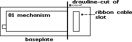
Please proceed with EXTREME CARE with this part, you only get one chance. The 71-drive slot in the 128D is identical to the length of the 81 front cover. Place the 81 cover over the 71-drive slot, leaving about 1/4" gap from the top of the 128D and draw around the 81 front cover. You now have a template to work to; I used 2 broken hacksaw blades to cut out the opening for the 81 cover, leaving about 1/8" around the mark. I then SLOWLY filed out the opening until the 81 cover fitted with a gentle tap, (place on a flat piece of wood to get a nice flush finish with the 128 cover). Once satisfied, I then removed the 81 cover, and super-glued and refitted..
Remove the original 71 drive from the main base plate that held it to the 128D, 4 x screws. Refit the base plate where it came from, securing with 2 x screws. Next refit the 128D front cover in the correct position and again use the original screws to temporary fix in position. Remove the 81 fixing plate and cut off the end as previously mentioned using tin snips or a hacksaw. Refit 81 mechanism and secure when done.
Next fit the 81 mechanism on to the base plate. Line up the drive with the front cover, making sure that the disk removal button slides into its original slot. Temporary hold in position, test that it is lined up by fitting a disk a few times and that the disk freely goes in and comes out of the 81 mechanism. Mark the position that the drive fits onto the old 71 base plate. Remove and drill the 4 holes you marked, I used a 1/8" drill. Since you have the original screws, re-use to secure the new drive to the old 71 base plate 4 x self-tapping screws. You can now secure the new drive to the old 71 base plate, but leave the front cover in its temporary state.
Before fitting the board, decide if you are going to fit device switches to replace the dipswitches (not recommended for the novice solderer, one slip up and the board will be kaput). Next you must insulate the bottom of the board. I used the original insulation from the drive, using insulation tape to secure them together. Before fitting, wrap insulation tape over the old metal post that used to hold the old 71-drive board in position. Just an extra precaution. This next step is a bit hard to explain, the new board will fit on the end of the base plate just like the old 71 used to with the metal post acting as a support. You can only access 2 screw holes and only 1 will line up. The left hand one, near the on/off switch. Fit a self-tapper into this hole; do not secure just yet. Examine the other end of the board. You will see that the holes fail to line up by about 1/2". I used a piece of plastic about 1" long and 1/4" wide, drill 2 x 1/8" holes after measuring their position, using self-tappers, secure the plastic to the board and base plate, secure all screws, not to tightly they only have to hold the board in position. Although the board is precariously perched, once all is finished it will never be moved--hopefully again. You can refit the Power/Drive Activity LED to the front cover of the 81 and secure, once you are satisfied that the board is OK.
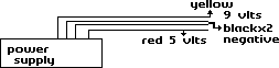
The 128D power supply has 3 leads coming from it. One supplies the main computer board; one the fan and the other the old 71 drive board. I recommend that you write down your findings for reference and any future projects. There are four wires that used to supply power to the 71, one YELLOW, two BLACKS and a RED (which are hopefully standard through out this range of computer). Using my voltage tester I found the following:
| YELLOW====9 volts | RED=====5 volts | BLACK====negative/return |
Cut off the old plug and strip about 1/2" of the insulation, I then tinned the wires which is to slightly solder each wire. Next measure how much wire you need to reach the 81 board, (the plug that supplies the drive mechanism with power). Probably about 8" is suffice. Again strip back the insulation around 1/2" and tin. Do this twice so that you will have 8 wires. The wire I used came from an old interior lamp and is about 1.5mm wire or around 1/8" in diameter, not quite as thick as the original you will be joining it to but it will do the job. Since this is part of the conversion could result in vaporizing your computer; it should be done with great attention. Since we will be connecting wires that are not Colour coded, a record of which wire is which is vital. My new wire came in three colours, brown, blue and green/yellow. I connected the two BLUES to the YELLOW-- (9 volts), twisted together and then soldered. Two BROWNS to the RED-- (5 volts), 2 of each BLACK to the GREEN/YELLOW-- (negative). Once all soldered, I insulated all connections with insulation tape. You now have the power cables to get to the 81 board and the drive mechanism.
If you did not manage to get any new plugs then the old can be used. The original cable that connected the 81 board to the drive mechanism can be cut in half and used. Again I hope the Colour coding is universal. I tested the voltage and found the following:
| RED===9 volts | BROWN===5 volts | BLACK===negative/return |
Now we have a nice mixture of colours to keep our eye on. Strip back the insulation on the wires you now have and tin like before. Now to join up. Using one end of the plug for the 81-drive board we connect as follows.
| YELLOW to BLUE to RED | == 9 volt supply. |
| RED to BROWN to BROWN | == 5 volt supply. |
| BLACK to GREEN/YELLOW to BLACK | == negative/return. |

Repeat the procedure for the other plug and when finished you should have one set of wires coming from the power supply with 2 wires of the same Colour coming from them.
If satisfied that all is correct and insulated, you can connect the plugs. One to the board and the other to the drive mechanism. The plugs will only fit in correctly one way but to be on the safe side--looking from the front of the computer, the BROWN on the plug should be the farthest away when connected to the board and the nearest when looking at the drive mechanism from the joystick port side. You can now test. Switch on and the power light LED should light up on the 81 front panel.. If not switch off and re-check all connections. You can now check how much ribbon cable you require, about 8" to 10" should be enough to replace the original, which is far to short now. You can take your original to your local computer man and have one made (recommended) or if you have the ribbon cable, strip the connectors from the old, notice that one plug faces DOWN whilst the other faces UP. The red line on the ribbon cable is called the key line, so long as you get this red line on the first notch all should be well. I used my fingers to partly grip the cable into the plug and then finished of in my vice. When complete connect to drive mechanism and control board. If you had been taking notes when you removed the old ribbon cable, you should have noticed that the key line--RED was to the left on both connectors, using the on/off switch as the left side. The on/off switch can be ignored, it is being by-passed but just to be safe--leave in the OFF position.
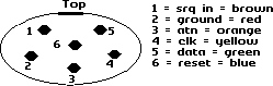
From the schematics in the programmer's ref guide, the internal drive is connected to the serial bus via CN7 and CN6 a seven pin post connector. Although the descriptions are correct and clearly visible, connections made to the schematics DO NOT WORK. Now that the controller board is in position, you can see how much cable you require to run from the serial connection on the board to CN7. Around about 7". Cut an original serial cable, which will hopefully have the same colours that I had (if not you will have to bell out each pin to find which Colour it is connected to). Strip back the outer sheaf approximately 2" and connect to a 7 or 6 pin female inline plug. If you could not get hold of a new plug you can, just like the drive board cut the original in half and uses that or solder the wires from the cable directly to CN7. All these methods will work, if the board has to be removed for some reason simply disconnect from the serial socket, just like you would do to remove a cable from an external drive. In the programmers ref guide is a good drawing of the serial port socket and the pin numbers and what each pin does.
The 6 pin din serial connector plug.
The above colours are what I found when I belled out each pin on the cable I cut. To be on the safe side and just in case I have made a mistake please check out your cable.
CN7 serial post connector.
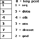
From the schematics in the programmer's ref guide, you will notice that the key post has moved from the bottom position, number 6 and moved to the top, position 0. It is not used nor connected. That is why you can use a 7 pin or 6-pin connector. The connections are as follows.
| 0 | Not Connected | |
| 1 | (SRQ) | to 1 -- BROWN |
| 5 | (DATA) | to 5 -- GREEN |
| 4 | (CLK) | to 4 -- YELLOW |
| 3 | (ATN) | to 3 -- ORANGE |
| 7 | (DRESET) | to 2 -- RED |
| 6 | Not Connected | |
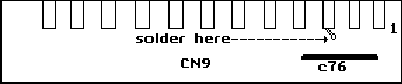
The observant amongst you will notice that the Blue wire on the cable is not included in the above. Although the above connections will work fine, there will be no reset to the new drive. To enable the reset you have to connect the BLUE wire from the serial cable to a reset on the main computer. The nearest reset to connect to is on the USER PORT (CN9) at position number 3. Behind the main user port is a pass through hole, this maybe open or filled with solder. Simply solder the BLUE wire to this point and you have DRIVE RESET.
Finally, decide what device number to set the drive to if you have not fitted external device switches. Alternately you could refit the top cover and user the carry handle to keep in place; the you can quickly remove and change the dipswitches if you want to. Just like an external drive. There is one more mod that you could do whilst the computer is open. Disable the new drive or the original for that matter completely, so that when you turn on the computer the drive will not be seen on the serial port bus. Fit a single pole switch between the ATN (attention) cable. Coloured ORANGE and marked 3 on the schematic. 1581 drive mechanism problems, fit one from the Amiga, it is identical. You will have twisted the ribbon cable 180 degrees, no UP and DOWN plugs on the Amiga connectors.
That's all there is to it, should take about 3-4 hours solid, take plenty of breaks and record what you have done.
One final point, you now have a spare 71-drive mechanism and controller board. Do not dispose of them because someone with a 1571 or 128D may need one, the 81 may break down or you could fit it into a 1570 case like I did but that is another story.
Still working fine. For a better finish and using an Amiga external drive mechanism could be fitted to the left of the keyboard connector. Thus leaving your 71 in tacked and replaceable if you have any problems.
Happy Computing,
Dave Elliott.
page URL: www.bigfoot.com/~c128page/c128d81/
contact: c128page@bigfoot.com