APPENDIX F
SCREEN AND COLOR MEMORY MAPS - C128 Mode, 40 Column and C64 Mode
NOTE: Follow this link for a lynx-friendly version.
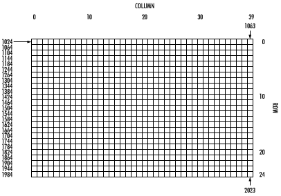
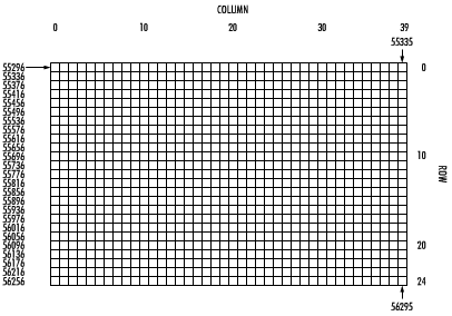
SCREEN MEMORY MAP, COLOR MEMORY MAP, Color Codes - 40 Columns
The following maps display the memory locations used in 40-column mode (C128 and C64) for identifying the characters on the screen as well as their color. Each map is separately controlled and consists of 1,000 positions.
The character displayed on the maps can be controlled directly with the POKE command.
F.1 SCREEN MEMORY MAP

The Screen Map is POKEd with a Screen Display Code value (see Appendix D). For example:
POKE 1024,13will display the letter {M} in the upper-left corner of the screen.
F.2 COLOR MEMORY MAP

If the color map is POKEd with a color value, this changes the character color. For example:
POKE 55296,1will change the letter {M} inserted above from light green to white.
F.3 Color Codes - 40 Columns
| 0 | Black | 8 | Orange | |
| 1 | White | 9 | Brown | |
| 2 | Red | 10 | Light Red | |
| 3 | Cyan | 11 | Dark Gray | |
| 4 | Purple | 12 | Medium Gray | |
| 5 | Green | 13 | Light Green | |
| 6 | Blue | 14 | Light Blue | |
| 7 | Yellow | 15 | Light Gray |
Border Control Memory 53280
Background Control Memory 53281